

Sputtering target cracking, arcing, and particle generation are common concerns in physical vapor deposition (PVD), but these problems do not always share the same root cause. Thermal stress, bonding defects, material porosity, surface deposits, cooling conditions, and process parameters can all influence target performance.
A target that develops cracks may have experienced excessive thermal stress or mechanical constraint. Repeated arcing may be associated with surface nodules, insulating deposits, inclusions, or process instability. Particle generation may involve material defects, erosion behavior, or contamination elsewhere in the deposition system.
For process engineers, the important question is not simply whether a target has failed. It is how to identify the mechanism behind the failure and determine whether the problem originates from the material, the bonded assembly, the cooling system, or the deposition process.
1. Five Common Sputtering Target Failure Modes
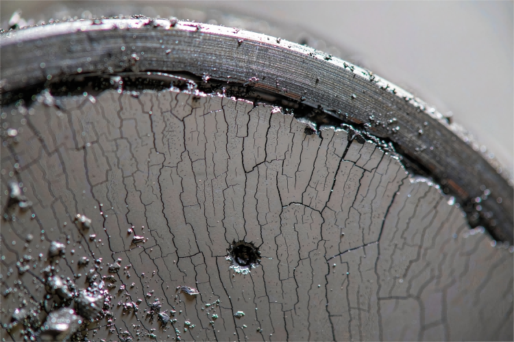
The first step in troubleshooting is to distinguish the observed failure from its possible cause. Cracking, debonding, arcing, particle generation, and nodule growth can occur independently or influence one another.
| Failure mode | Typical symptoms | Possible contributing factors | Useful inspection points |
| Target cracking | Visible fractures, edge cracks, or cracks discovered after cooling | Thermal gradients, mechanical stress, mounting conditions, material defects | Crack location, operating history, mounting condition, material structure |
| Bonding failure or debonding | Separation between target and backing plate; changes in thermal behavior | Bond-layer defects, thermal cycling, incompatible expansion, assembly stress | Bond interface, available inspection records, temperature trends |
| Arcing | Voltage instability, localized arc events, craters, or burn marks | Surface deposits, nodules, insulating inclusions, reactive process conditions | Erosion track, surface deposits, arc history, process settings |
| Particle generation | Particles or defects on deposited films | Surface flaking, inclusions, pores, unstable deposits, chamber contamination | Wafer or substrate defect map, target surface, chamber condition |
| Nodule growth | Raised deposits on the erosion track, sometimes followed by arcing | Re-deposition, reactive sputtering conditions, local surface chemistry | Nodule distribution, gas control, accumulated operating time |
These symptoms should be interpreted in context. For example, a particle defect on a coated substrate does not automatically prove that the target material is responsible. Chamber shields, process residues, fixtures, and other components can also contribute particles.
A useful investigation therefore begins with the defect pattern and operating history rather than an immediate decision to replace the target.
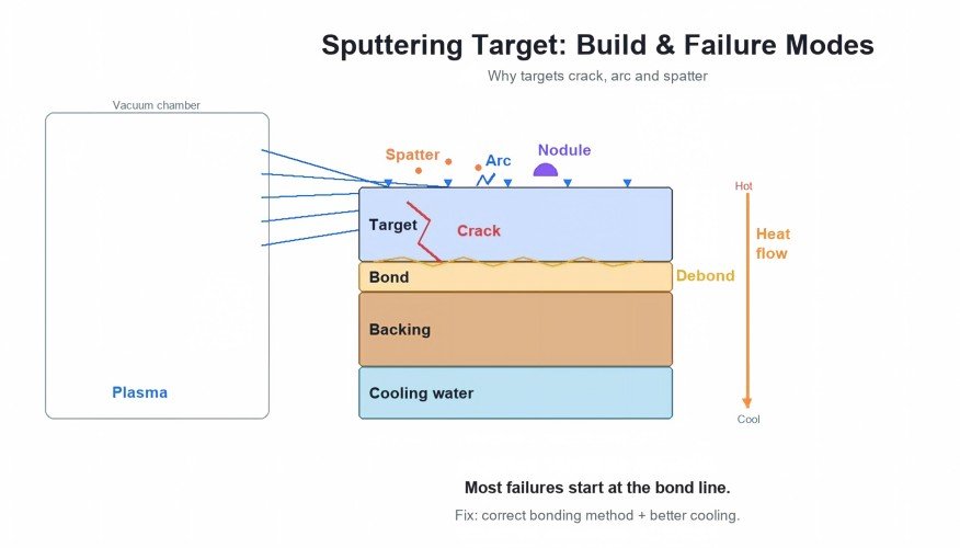
2. Sputtering Target Cracking: Understanding Thermal Stress
Thermal stress is an important factor in sputtering target cracking, particularly when the target operates under high thermal load or experiences uneven heating and cooling. During magnetron sputtering, energetic ions bombard the target surface. Part of the input energy contributes to material removal, while a substantial portion becomes heat. This heat must travel through the target material, any bonding layer, the backing plate, and finally the cooling system.
Each part of this thermal path contributes resistance to heat transfer. The temperature distribution depends on several factors, including material thermal conductivity, component thickness, contact quality, cooling-channel design, coolant flow, and operating power. A local increase in thermal resistance can produce a temperature difference across the target assembly. When different regions expand by different amounts, internal stress develops. If the stress exceeds the material’s ability to accommodate deformation, cracking may occur.
Thermal expansion mismatch: Different target and backing materials do not expand equally when heated. The coefficient of thermal expansion (CTE) describes how much a material changes in size with temperature. For a simplified comparison, copper generally expands more than many ceramic materials. When a ceramic target is attached to a copper backing plate, repeated temperature changes can place stress on the target and the interface. The actual stress depends on more than CTE alone. Target geometry, thickness, bonding method, mechanical restraint, temperature distribution, and thermal cycling all influence the final condition.
| Material | General thermal behavior | Consideration in target assemblies |
| Copper | High thermal conductivity and relatively high thermal expansion | Common backing material; provides effective heat spreading but may create expansion mismatch with ceramics |
| Molybdenum | Lower thermal expansion than copper and good high-temperature stability | May be considered where dimensional stability and material compatibility are important |
| Titanium | Relatively low thermal conductivity compared with copper | Local heat distribution and target geometry should be considered |
| Indium | Soft, ductile bonding material with a relatively low melting point | Can accommodate some mechanical strain, but its operating limits must be respected |
| Alumina | Electrically insulating and relatively brittle | Thermal gradients and mechanical constraints require careful consideration |
These are general material characteristics, not a universal design specification. Actual values vary with grade, purity, temperature, and material condition. The suitability of a target assembly should be evaluated using the specific material data and operating conditions.
What to check when a target cracks
Before concluding that the target material is defective, review:
- Whether the crack begins at an edge, mounting feature, or another localized region.
- Whether the target experienced a rapid power increase or temperature change.
- Whether cooling flow and coolant temperature remained stable.
- Whether the target was installed with appropriate mechanical support and mounting conditions.
- Whether the target or backing plate showed signs of distortion or damage.
- Whether the material documentation identifies relevant density, composition, or microstructure characteristics.
Crack location is useful evidence, but it is not sufficient by itself to establish the root cause.
3. Sputtering Target Bonding: Why the Interface Matters
In a bonded sputtering target assembly, the target material is joined to a backing plate through a bonding layer or bonding process. This interface has two important roles: maintaining mechanical integrity and transferring heat away from the target.
If the bond is incomplete, damaged, or unsuitable for the operating conditions, local heat transfer may become less effective. This can contribute to temperature differences, mechanical stress, and changes in target performance.
Three bonding approaches commonly discussed for sputtering target assemblies are indium bonding, elastomer bonding, and diffusion bonding. Their suitability depends on the target material, backing plate, operating temperature, power conditions, vacuum requirements, and equipment design.
Indium bonding
Indium is a soft, ductile metal with a relatively low melting point. Its compliance allows it to accommodate some differential thermal expansion between the target and backing plate.
However, indium bonding also has temperature limitations. Indium melts at approximately 156.6 °C, but this value should not be treated as a universal operating limit for every bonded assembly. The acceptable temperature range depends on the complete assembly design, local temperature distribution, operating conditions, and appropriate safety margins.
When evaluating an indium-bonded target, pay attention to bond-layer continuity, target geometry, thermal loading, and the operating limits specified for that particular assembly.
Elastomer bonding
Elastomer bonding uses a compliant polymer-based layer between the target and backing plate. Its flexibility may be useful for certain ceramic target configurations where mechanical stress needs to be accommodated.
The polymer grade and assembly design are important. Vacuum compatibility, outgassing, thermal resistance, temperature capability, and long-term stability should all be considered. Elastomer bonding should not automatically be assumed suitable for high-power or high-temperature operation.
Diffusion bonding
Diffusion bonding creates a metallurgical connection through controlled temperature and pressure. It can be considered for material combinations and applications where a conventional soft bonding layer is not appropriate.
However, the process requires careful consideration of material compatibility, thermal expansion, processing conditions, and dimensional stability. A strong metallurgical interface does not eliminate the possibility of cracking if the target and backing materials experience excessive thermal or mechanical stress.
What should procurement teams confirm?
Before selecting a bonded target, clarify the bonding method, target and backing-plate materials, applicable operating conditions, and available inspection documentation.
Where ultrasonic inspection is suitable for the material, geometry, and interface, a C-scan may help identify and map unbonded regions. However, inspection sensitivity and interpretation depend on the inspection procedure and assembly configuration. A C-scan result should therefore be assessed against acceptance criteria established for the specific target rather than a universal percentage.
For further material selection, compare the available metal sputtering targets, ceramic sputtering targets, and alloy sputtering targets according to the intended deposition application.
4. Sputtering Target Porosity: How Density Affects Performance
Relative density is an important material characteristic for many sputtering targets. It compares the measured density of a material with its theoretical density.
Consider two simplified examples:
A relative density of 99.5% corresponds to a theoretical pore-volume fraction of approximately 0.5%, assuming the density measurement and theoretical reference are appropriate.
A relative density of 99.9% corresponds to approximately 0.1%.
The calculated pore-volume fraction at 99.5% is five times that at 99.9%.
This comparison illustrates why small differences in relative density can represent meaningful differences in total pore volume. However, it does not mean that a target with 99.5% density will generate five times as many particles as one with 99.9% density.
The effect of porosity depends on pore size, distribution, connectivity, location, and the surrounding microstructure. Other characteristics, including inclusions, grain boundaries, phase distribution, and surface condition, can also influence sputtering behavior.
Why porosity deserves attention
Thermal behavior: Pores can reduce the effective thermal conductivity of a material, depending on their amount and distribution. Local thermal differences may become more significant when porosity is concentrated in particular regions.
Mechanical integrity: Pores and weakly bonded regions can act as stress concentrators. Under thermal cycling or mechanical loading, these regions may contribute to crack initiation or propagation.
Surface exposure during erosion: As sputtering removes material, internal pores or inclusions may become exposed at the target surface. Their influence depends on their size, structure, and interaction with the plasma.
Particle generation: Weakly attached material or unstable surface regions can contribute to particle formation. Nevertheless, particle behavior also depends on deposition conditions, target surface chemistry, and chamber cleanliness.
Density should not be evaluated alone
A useful material evaluation should consider relative density together with composition, purity, microstructure, and the intended sputtering conditions.
The measurement method must also be appropriate for the material. Archimedes-based methods, for example, require attention to sample preparation, open porosity, liquid penetration, and the applicable material standard. ASTM B962 and ASTM B311 have specific scopes and should not be treated as interchangeable methods for every metal or ceramic target.
For ceramic materials, the appropriate density method and acceptance range depend on the material system and manufacturing route. A single density threshold should not be applied to every ceramic target.
When comparing target specifications, request the measured result, measurement method, and batch identification rather than relying only on a general statement such as “high density.”
5. Sputtering Target Arcing and Particle Generation: Process-Side Factors
Even a target with suitable material properties can experience unstable operation if process conditions are not controlled. Several process-side factors deserve attention when investigating repeated arcing or increased particle generation.
Power density and power changes
Power density influences the thermal load on the target. Its practical effect depends on the effective erosion area, target geometry, cooling design, and bonding configuration.
A target qualified under one operating condition should not automatically be assumed suitable for a substantially higher power level. Review the actual power profile and compare it with the target assembly’s documented operating limits.
Rapid power changes may also create thermal transients. A controlled power ramp, where supported by the equipment and process recipe, can help reduce abrupt temperature changes. The appropriate ramp profile should be established for the specific system rather than copied as a universal time setting.
Cooling-water performance
Cooling performance can change even when the process recipe remains the same. Possible causes include:
Reduced coolant flow.
Increased inlet-water temperature.
Fouling or deposits in cooling channels.
Partial blockage or leakage.
Changes in the cooling-system configuration.
Compare flow, inlet temperature, outlet temperature, and pressure with the system’s commissioning baseline. A change in outlet temperature alone should not be interpreted without considering flow rate and applied power.
Reactive sputtering and surface deposits
In reactive sputtering, the introduction of oxygen, nitrogen, or another reactive gas changes the chemical conditions at the target surface.
Depending on the material and process, insulating compounds or deposited material may form on parts of the target surface. These changes can influence discharge behavior and contribute to arcing.
Nodules may also develop as material accumulates or re-deposits on the erosion track. If deposits become unstable, they may detach or contribute to localized discharge events.
Inspect the erosion track and review reactive gas flow, pressure, power, and arc history before assuming that the incoming target material is responsible.
Erosion profile and target life
As the target is used, its surface geometry changes. Non-uniform erosion can create localized changes in heat distribution and material removal.
Near the end of target life, the remaining material thickness and erosion profile may affect thermal behavior and mechanical stability. A sudden increase in particles or arc events should therefore be reviewed against cumulative operating time and the measured erosion profile.
6. Sputtering Target Troubleshooting: An Eight-Step Inspection Checklist
A structured troubleshooting process helps separate material-related problems from process and equipment issues. The following sequence starts with operating records and visual observations before moving to more involved inspection.
| Step | Inspection point | What to review |
| 1 | Identify the dominant symptom | Cracks, arc events, nodules, or substrate particles |
| 2 | Review process history | Power, pressure, gas flow, ramp profile, and operating time |
| 3 | Check cooling performance | Flow rate, inlet/outlet temperature, pressure, and baseline trends |
| 4 | Inspect the target surface | Erosion track, deposits, discoloration, cracks, and visible damage |
| 5 | Evaluate erosion profile | Erosion depth and uniformity across the target |
| 6 | Review bonding condition | Available bonding records and suitable inspection results |
| 7 | Review material documentation | Composition, purity, density, and available impurity data |
| 8 | Compare defect patterns | Wafer or substrate maps, target position, and chamber condition |
The order may change depending on the severity of the failure and equipment safety requirements. A visibly fractured target, for example, should not be returned to operation simply to collect additional process data.
The purpose of the checklist is to build an evidence-based explanation. Replacing the target without reviewing cooling, mounting, process history, and chamber condition may solve the immediate problem without preventing it from happening again.
7. What to Specify When Purchasing a Sputtering Target
A purchase order should describe more than the chemical formula and external dimensions. Material characteristics, inspection requirements, and assembly conditions should be defined according to the intended application.
Before placing an order, consider the following points:
- Material composition: Specify the chemical formula, alloy ratio, or required composition range. For multi-element materials, clarify the acceptable composition variation where relevant.
- Purity: Define the required purity level and how impurities should be reported. Request batch-specific composition data or trace-element information where necessary.
- Density: State the required relative density and an appropriate measurement method. Ask for the measured result rather than relying only on a typical value.
- Microstructure: Where relevant, define grain-size or structural requirements and clarify what supporting documentation is available.
- Dimensions: Confirm diameter, length, thickness, tolerances, geometry, and any machining or mounting requirements.
Bonding: For bonded assemblies, specify the - bonding method, target and backing-plate configuration, and applicable operating requirements.
- Surface condition: Define the required surface finish and visual acceptance criteria. If roughness is important, state the measurement method and applicable standard.
- Traceability: Request batch or serial identification so that the supplied unit can be linked to its relevant documentation.
Not every specification applies to every material. For example, a grain-size requirement may be relevant to some metallic targets but inappropriate or insufficient for a particular ceramic material. Similarly, density measurement methods must be selected according to the material and its porosity characteristics.
Standards such as ASTM E112 for grain-size determination and the ISO 21920 series for surface texture may be relevant where their scopes match the material and measurement requirements. The applicable edition and method should be agreed upon in the purchase specification. A useful purchase order makes the acceptance criteria measurable. Instead of requesting “high density” or “fine grain,” specify the required value or range, the measurement method, and the documentation expected with the material.
8. Choosing the Right Target Material: Metal, Alloy, or Ceramic?
The target material should be selected according to the required film composition, deposition process, equipment configuration, and operating conditions.
Metal sputtering targets
Metal targets are used where the deposited film requires a metallic element or where the metal serves as a source material for a subsequent reaction or compound-forming process.
Thermal conductivity, mechanical properties, purity, composition, and target geometry are relevant selection factors. For applications requiring a specific metal, compare the material grade and available specifications rather than relying on the material name alone.
Explore the ULPMAT metal sputtering target range to review available material options.
Alloy sputtering targets
Alloy targets provide a source containing multiple metallic elements. Composition uniformity and the relationship between target composition and deposited film composition should be considered, particularly where film stoichiometry is important.
The appropriate alloy composition depends on the required film properties and deposition route. Engineers should confirm the nominal composition, allowable variation, and available batch documentation before selecting a target.
View the ULPMAT alloy sputtering target range for available material options.
Ceramic sputtering targets
Ceramic targets are widely used for oxide, nitride, and other compound films. Their electrical behavior, brittleness, density, thermal properties, and bonding configuration may require different operating and handling considerations from metallic targets.
For example, engineers evaluating oxide materials can review ULPMAT’s Magnesium Aluminate (MgAl₂O₄) sputtering target and Zirconium Oxide (ZrO₂) sputtering target pages.
The correct selection cannot be determined from material name or purity alone. Target dimensions, backing configuration, bonding requirements, power conditions, and the desired film properties all need to be considered together.
FAQs
Sputtering target cracking may result from thermal gradients, mechanical stress, mounting conditions, bonding problems, or material defects. The crack location, operating history, cooling performance, and assembly configuration should be reviewed before assigning a root cause.
Arcing can be associated with insulating surface deposits, nodules, inclusions exposed during erosion, and unstable reactive sputtering conditions. Process settings, target surface condition, and arc history should be evaluated together.
Bonding problems can contribute to localized thermal resistance and mechanical stress. However, cracking does not automatically indicate a bonding defect. Target material properties, geometry, mounting, and process conditions should also be considered.
No. Higher relative density generally indicates a lower total pore volume, but particle generation also depends on pore distribution, inclusions, microstructure, surface condition, erosion behavior, and process stability. Density should be evaluated alongside other material characteristics.
Possible indicators include changes in thermal behavior, temperature trends, and evidence of interface separation. Where suitable for the assembly, ultrasonic inspection such as C-scan may help evaluate the bond interface. The inspection procedure and acceptance criteria must be appropriate for the specific configuration.
Late-life particle generation may be associated with changes in target thickness, erosion profile, surface condition, exposed inclusions, or chamber contamination. Comparing defect maps with cumulative operating time and target erosion measurements can help identify the cause.
Purity is important, but it is not the only factor. Composition uniformity, density, microstructure, target geometry, bonding condition, cooling performance, and process parameters can all influence sputtering behavior.
Conclusion: A Target Failure Is a Clue, Not a Diagnosis
Sputtering target cracking, arcing, and particle generation should not be treated as interchangeable problems. Each symptom provides a different clue, and the actual cause may involve the target material, bonding interface, cooling system, deposition recipe, or chamber condition.
A practical investigation begins by identifying the failure mode, reviewing process and cooling records, examining the erosion surface, and checking the available material and assembly documentation. Only after these factors have been considered should the investigation conclude that the target material itself is responsible.
But there is one question that deserves attention before the next target is ordered:
If two targets have the same composition and purity, why can they still behave differently in the same sputtering system?
The answer may involve characteristics that are not obvious from a product name or a purity value alone—including microstructure, density distribution, bonding configuration, dimensions, and compatibility with the operating conditions.
If you are comparing target specifications or investigating an unexpected failure, contact ULPMAT with the target material, dimensions, bonding configuration, and a description of the problem. You can also explore the available metal, alloy, and ceramic sputtering target selections to identify materials for further evaluation.
Not sure whether the problem comes from the target, the bond, or the process? Send us the details of your application and the symptoms you have observed. The right questions are often the first step toward finding the real cause.
Published by: ULPMAT Materials Knowledge Center
Company: UltraPurMat Group Co., Ltd.
Last updated: October 30, 2026